Name: | Create custom sections using polygonal shapes |
Description: | Create custom cross sections by drawing polygonal shapes within the section designer, then modify or add to their geometry through reshape mode or interactive database editing. |
Program: | SAP2000 |
Version: | 14.2.0 |
Model ID: | na |
Custom cross sections may be created in the Section Designer by using polygonal shapes. Interactive database editing then enables the efficient modification of section geometry. To demonstrate, this tutorial provides guidelines for using the Section Designer to model an AASHTO I-Beam Type I section.
The modeling process is as follows:
- Create a new section by selecting Define > Section Properties > Frame Sections > Add New Property.
- Select Frame Section Property Type > Other, then click on Section Designer to open SD Section Data.
- Select Section Designer to launch the Section Designer.
- Initialize 1in grid spacing to draw the section. Select Options > Preferences, then set the Background Guideline Spacing to 12in and the Fine Grids between Guidelines to 11, as shown in Figure 1:

Figure 1 - Guideline and Fine grid spacing
- Select Draw > Draw Poly Shape, then draw the section by snapping on intersecting grid lines, as shown in Figures 2 and 3:

Figure 2 - Draw section

Figure 3 - Section drawn
- Save the model, then switch to reshape mode by selecting Draw > Reshape Mode. Any section point may now be repositioned within the cross section by clicking on the section, then by clicking on the black square and holding the button down while dragging to the new position, as shown in Figure 4:

Figure 4 - Reshape mode
Additional points may be added along the cross-section boundary by using interactive database editing.
For example, a slab may be adjoined above the girder through the following process:
- Open interactive database editing by selecting Edit > Interactive Database Editing.
- Select the three tables under Model Definition > Property Definitions > Section Designer Properties, then select OK, as shown in Figure 5:

Figure 5 - Interactive database editing
- Select To Excel, as shown in Figure 6, to export this data to Excel.

Figure 6 - To Excel
- In Excel, add another four points to represent the perimeter of the slab, then select From Excel. These points are then within the section definition, as shown in Figure 7:
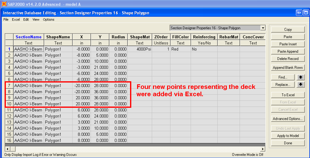
Figure 7 - From Excel
- Open the section within the Section Designer to display the final cross section, as shown in Figure 8:

Figure 8 - Final section