A simple model of a tall cruciform building with vertical walls and flat slabs exhibits very different buckling behavior depending on whether or not rigid diaphragms are used for the floors. The study which follows investigates such systems, and the conclusions drawn are described as follows:
Summary and Conclusions
- With rigid diaphragms, torsional buckling of the whole structure is one of the fundamental buckling mode.
- Without rigid diaphragms, torsional buckling occurs at a higher buckling factor.
- Making the slab stiffer in plane, but without using a diaphragm constraint, does not substantially change this behavior.
- The presence of the diaphragm constraint allows significant horizontal compressive stresses to develop in the walls. These are due to Poisson’s effect under gravity load, and are sustained by the infinitely stiff horizontal diaphragm.
- Without the diaphragm, even with a very stiff slab, the Poisson stresses are less pronounced.
- The horizontal compressive stresses in the walls cause out-of-plane instability, tending to cause torsional buckling.
- With the diaphragm constraint, the corresponding tension in the slab is implicitly developed but no slab stresses are computed. Therefore, there is no tension stiffening included in the P-delta formulation.
- With the stiff or flexible diaphragm, the tension in the slab that resists the horizontal Poisson stresses is included in the P-Delta effect. This tension stiffening counteracts the softening due to the compressive stresses in the wall.
- Vertical compressive stresses do not have a counteracting tensile stress in the slab, and will tend to cause torsional and other types of buckling.
- To prove this analysis, setting Poison’s ratio to zero causes the model with diaphragm constraints and the model with a stiff slab to be essentially identical, with a high torsional buckling factor.
- All conclusions above are for the particular model of this study. Whether or not they apply to any other model or real structure is a decision to be made by the engineer.
- Whether or not these horizontal stresses can be sustained in a real structure is a modeling decision for the engineer. However, the effect on structural behavior is very significant and merits careful consideration.
SAP2000 Model
- All walls and floors are 12’ x 12’ x 8” concrete thin-shell objects.
- 16 stories
- Buckling under self-weight load
Three similar structures
- Center – No modification (flexible diaphragms)
- Left – Slab stiffness modifiers of 1000 for F11, F22, F12 (stiff diaphragms)
- Right – Diaphragm constraints (rigid diaphragms)

Figure 1 - SAP2000 model with three variations on diaphragm design
Vertical stresses under self-weight
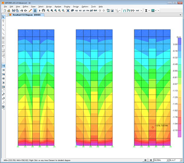
Figure 2 - Vertical stresses under self-weight
Horizontal stresses under self-weight

Figure 3 - Horizontal stresses under self-weight
Slab stresses at Story 2 (top) and Story 8 (bottom)
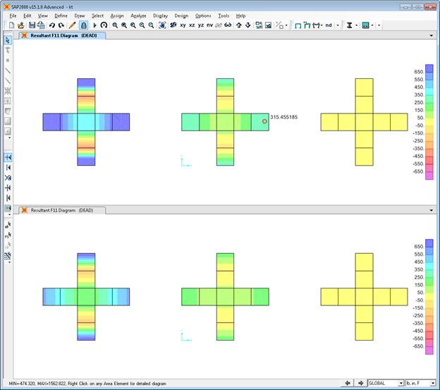
Figure 4 - Slab stresses at Story 2 (top) and Story 8 (bottom)
Buckling modes 1, 2, 3

Figure 5 - Buckling modes 1, 2, 3
Buckling modes 4, 5, 8

Figure 6 - Buckling modes 4, 5, 8
Buckling modes 6, 7, 9

Figure 7 - Buckling modes 6, 7, 9
Buckling modes 10, 11, 12

Figure 8 - Buckling modes 10, 11, 12
Buckling modes 13, 14, 15

Figure 9 - Buckling modes 13, 14, 15
Buckling modes 16, 17, 18

Figure 10 - Buckling modes 16, 17, 18
Buckling modes 19, 20, 21

Figure 11 - Buckling modes 19, 20, 21
Buckling modes 22, 23, 24

Figure 12 - Buckling modes 22, 23, 24
Buckling deformation of Stories 2 and 8

Figure 13 - Buckling deformation of Stories 2 and 8
Buckling Factors

Figure 14 - Buckling Factors