Nonprismatic frame objects should initially be drawn with a constant cross section, then assigned a tapered section definition. To begin, select Define > Section Properties > Frame Sections to ensure that the start and end sections of the tapered frame are available in the Frame Properties menu, shown in Figure 1:
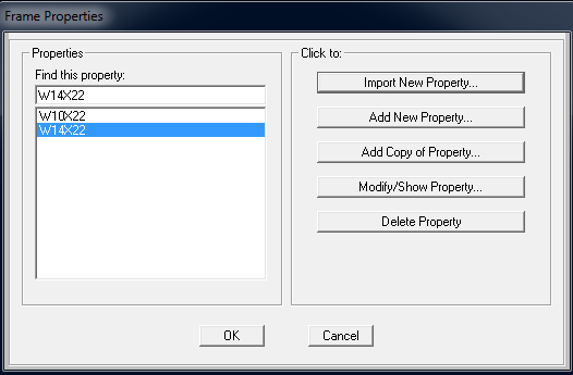
Figure 1 - Frame properties menu
To import sections, select Import New Property, then click the icon for section type. Scroll down to select the section database, labeled SECTIONS8.PRO, and add any sections desired for modeling. To define a nonprismatic frame section, select Add New Property > Other on the scroll-down menu, then select the Nonprismatic icon, shown in Figure 2:

Figure 2 - Add non-prismatic frame section
Next, name the section, specify the start and end sections associated with object taper, and specify segment Length as 1.0 and Length Type as Variable. This applies taper as a ratio of the length between each node. The Absolute option correlates with exact taper length. Finally, specify how moment of inertia varies. Wide-flange sections are parabolic in major and linear in minor directions. Select ADD to complete the definition, and OK to complete the process, as shown in Figure 3:

Figure 3 - Define non-prismatic frame section
To model a series of tapered segments within a single member, follow the same process while adjusting the Length definition in proportion to each tapered segment.
Now that the tapered section is defined, select the objects to be tapered, then assign the tapered section by selecting it from the options under Assign > Frame > Frame Sections.
The Set Display Options command (indicated by the check-box icon) gives users control over model views. Users may enable Local Axes to ensure that start and end nodes are as desired for tapered objects. Users may also enable the Extrude View feature to review the profile of section depth.
Notes
- Because nonprismatic frame-section properties vary along the length of the object, weight and other properties may be displayed per segment, after analysis is run, through Miscellaneous Data > Material List.
- Complex extruded members created using the Section Designer are displayed as the rectangular bounding box which encloses the object.
See Also
The SAP2000 Tutorial 06 - Nonprismatic Sections of the CSI Watch & Learn video series presents a useful demonstration on this topic.