...
| live- |
|---|
...
| template | ||
|---|---|---|
|
Default modeling procedures locate object boundary conditions along the centroid of the cross section. When a simply supported
...
(pin-pin)
...
...
object
...
is
...
modeled
...
with
...
a
...
top-center
...
or
...
bottom-center
...
insertion
...
point
...
,
...
internal
...
...
are
...
generated
...
which
...
have
...
the
...
effect
...
of
...
a
...
vertical
...
offset.
...
A
...
kinematic
...
result
...
of
...
this
...
modeling
...
technique
...
is
...
the
...
generation
...
of
...
longitudinal
...
forces
...
which
...
act
...
on
...
an
...
arm
...
about
...
the
...
neutral
...
axis.
...
If
...
this
...
behavior
...
is
...
not
...
desired,
...
one
...
support
...
may
...
be
...
changed
...
from
...
a
...
pin
...
to
...
a
...
roller
...
condition
...
such
...
that
...
horizontal
...
reactions
...
are
...
released.
...
This
...
behavior
...
may
...
be
...
exhibited
...
when
...
...
...
are
...
supported
...
by
...
...
...
located
...
at
...
the
...
bottom
...
of
...
the
...
bridge
...
girders.
...
Presented in Figure 1 are visuals which depict how standard and offset objects:
- Are displayed in the software interface.
- Are kinematically related to the analytical model.
- Respond under flexural loading.
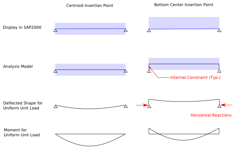
Figure 1 - Simply-supported beam with center and bottom-center insertion points
The images from Figure 1, as they appear in SAP2000, are given in Figure 2:
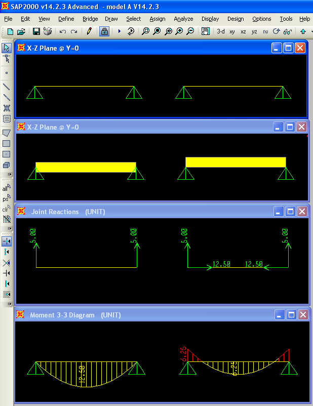
Figure 2 - Images as they appear in SAP2000
See Also
- Area object offset article
Attachments
- SAP2000 V14.2.3 model (zipped SDB file)