...
| live-template | ||
|---|---|---|
|
The internal forces and capacities of a beam are calculated with respect to the cross-section center of gravity. This test problem studies the modeling of a rectangular and continuous beam which is solid along the left segment and hollow along the right. This void is located along the bottom of the element.
Default insertion-point settings locate each segment such that the center of gravity aligns with the element chord. As shown in the image at the top of Figures 1-4, this results in misalignment between each segment because the center of gravity is higher for the hollow section. This may be corrected through either of the following methods:
- Draw element chords to account for the difference in center-of-gravity location, as shown in the middle image of each figure.
- Use a bottom-center insertion point to draw the two segments along the same line as shown in the bottom image of each figure.
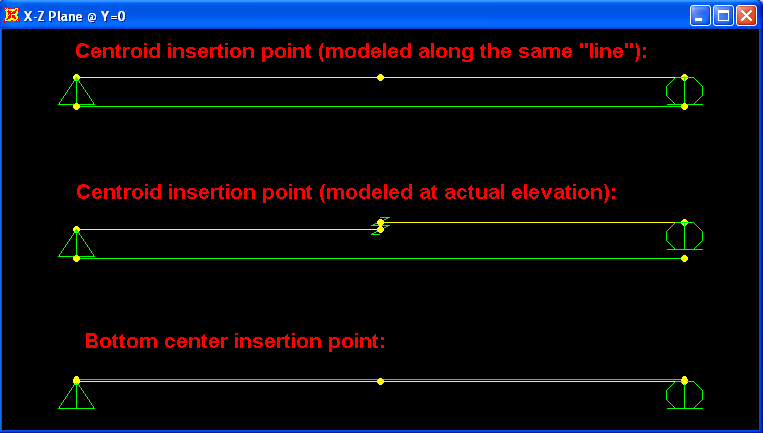
Figure 1 - Modeling approaches

Figure 2 - Corresponding depth profile
To demonstrate how each of these conditions affects response, a straight tendon is modeled below each beam. Tendon deflection and internal moment (relative to cross-section centroid) is presented. Results are correctly reported only for the second and third case, where the solid and hollow sections properly align.

Figure 3 - Displacement

Figure 4 - Moment
Attachments
- SAP2000 V14.2.0 model (zipped SDB file)
| Show If | ||
|---|---|---|
| ||
Related Incidents:
| ||
| {live-template:Test Problem}
When modeling beams, the internal forces and capacities are calculated with respect to the center of gravity of the cross section.
This test problem studies and model of continuous beam of a rectangular cross section with solid cross-section in the left portion of the span and with hollow section (with the void located at the bottom of the section) in the right portion of the span.
When the beams representing the left and right portions of the span are drawn along the same line and the default center of gravity insertion point is used, the sections are not physically placed in the correct location as shown in the top beam in the Figures below. This is due to the fact that the center of gravity for the hollow section is higher and the two section therefore become misaligned. There are several approaches that can be used to correct this:
(1) Drawn the lines representing the beams at their "correct" center-of-gravity location as shown for the middle beam in the Figures below.
(2) Use bottom center [insertion point|kb:insertion point] and draw the two beams along the same line as shown for the bottom beams in the Figures below.
!geometry.png!
!extruded shape.png!
To demonstrate how are the internal forces affected for the three cases, draw a straight tendon placed at fixed distanced from the bottom of the beam. The deflections and internal moments are presented below. Note that the internal moments (relative to the centroid of the cross-section) are reported correctly only for the middle and bottom beams. This is due to the fact that these two beams were modeled in their correct physical location, either by using bottom center insertion point or by drawing the members at their actual center-of-gravity.
!deformed shape.png!
!moment diagrams.png!
h1. Attachments
* [SAP2000 V14.2.0 model|^SAP2000 V14.2.0 model A.zip] (Zipped SDB file)
{related-incident:no=25048|comment=Aligning solid and hollow sections.} |