How are area objects drawn and offset?
Extended Question: I am using area objects to model an underground vault subjected to soil pressure. Which of the elevation sketches provided is the best approach to modeling?
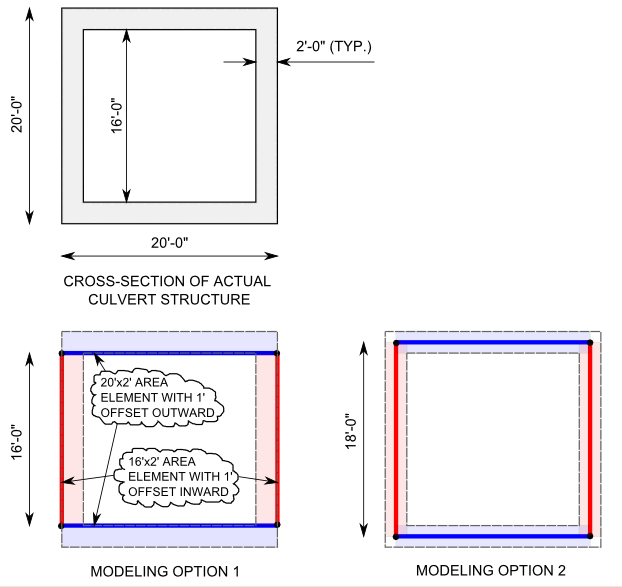
Figure 1 - Elevation views
Answer: It would be reasonable to model the vault according to either of the sketches provided. Another option would be to model all area objects at their midplanes such that a slight overlap occurs at the corners. While useful for obtaining global response, any of these modeling techniques will be approximate, given that shell formulation is a special 3D-elasticity case which itself is inherently approximate.
It may be best to use 3D solid objects if the wall thickness becomes sufficiently large relative to overall dimensions, or if detailed results at the corners are of interest.
| Hidden content |
|---|
|
Question
I am making a simple concrete box model in SAP2000. It is an underground concrete vault and sketch below shows elevation view. The top portion shows the actual dimensions and the bottom portion is what I think to make an analysis model. Is it the proper and best way to model to obtain proper member forces? The loadings are soil pressures from outside the vault.

Answer
Setting up the model according to your sketch would be reasonable. All area objects could be also modeled at their midplanes with a slight overlap at the corners. Both approaches would be adequate for obtaining global response, but it is important to remember that shell elements (by their very nature) are approximate and special case of three-dimensional elasticity.
...
|