Pipe Supports
CSiPlant offers a suite of commonly used pipe supports for convenient modeling of boundary conditions. Pipe supports can be added to a group of selected point objects using Insert commands or Assign>Joint options. Supports can also be added using Draw commands. Selected pipe supports can be changed, rotated, or connected to another point using 2-point supports using one of the Assign>Support options.
CSiPlant pipe supports offer several unique capabilities to be aware of:
- CSiPlant pipe supports automatically connect to the outside diameter (OD) of the pipe with internal rigid links automatically generated from pipe centerline to the OD in each acting direction of the support.
- Anchors, guides, line stops, and distributed supports automatically follow the local axis of piping and frames. Local support reactions can be graphically viewed and reported for supports on skewed pipelines that don’t align with global axes.
- Guides, vertical stops, line stops, and distributed supports enable users to define different gaps, different friction coefficients, and different linear or multi-linear spring properties in each acting direction of the support. For example, a guide support could be defined to have a 2" gap to the right (local 3 direction) with friction coefficient of .3, with 0 gap to the left with a multi-linear breakaway spring.
- Once a pipe support has been defined, it can be reused without having to reenter support data, thereby saving time, and improving consistency by enabling users to create their own customized library of pipe supports.
- Damper/Snubber support not only applies stiffness (K), it can also apply a damping constant for energy dissipation (C) with nonlinear velocity exponent option as specified by some damper vendors. If a damper works with a column of fluid, there must be an energy dissipation aspect to its behavior in addition to stiffness. The damping properties of nonlinear viscous dampers are based on the Maxwell model of viscoelasticity (Malvern, 1969), and may be specified for each deformational degree-of-freedom (DOF).
- All pipe supports can be applied as either a 1-point support connected to ground (default), or as a 2-point support connected to another pipe or frame element.
Pipe support local axes can easily be rotated at any angle. Select 1 or more pipe supports, then Assign>Support>Local axes. Below is an example of a guide support with rotated local axis to model a roller support.

Anchors and guides align with local axis of the skewed pipeline

Users can create their own library of customized pipe supports within each support type category. Support properties can be different in each acting direction. Distributed supports are assigned to selected elements (not joints) on a per unit length basis and are typically used for soil modeling. Distributed supports can be assigned to pipe and frame elements, enabling users to model buried pipelines or pipelines resting on soil, as well as buried piles.

As a supplement to pipe supports, CSiPlant also offers 1-point and 2-point link objects for modeling specialized force-deformation relationships for applications such as base isolators, damper friction springs, and yielded damper coefficient behavior.
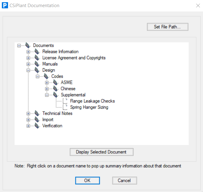
See CSiPlant Help menu>Documentation>Design>Codes>Supplemental to view the 7-page "Spring Hanger Sizing" documentation for more details on CSiPlant's spring hanger design options.