...
| live- |
|---|
...
| template | ||
|---|---|---|
|
On this page:
| Table of Contents |
|---|
Model description
- Create a new model from template. Define as a simple span, 40m long, with steel girders cross-section.
- Release the bearing at the end abutment to achieve a simply supported condition.
- Define point, line, and area loads in separate load cases as follows:
- Point load: 10kN load applied at station 20, centered transversely.
- Line load: 1kN/m load applied between stations 15 and 25, centered transversely.
- Area load: 0.1kN/m^2 load applied between stations 15 to 25 and across the width of the deck.
These loads will all cause an effect equivalent to loading the bridge midspan with a 10kN point load
- Run the analysis and check the midspan moments. For point loading, the theoretical midspan moment is given as follows:

Plan, elevation, and section diagrams depicting load application are given in Figure 1:

Figure 1 - Load application diagrams
Model development
Define and apply loads
Use the Loads > Loads - Point command to define a new point load, as shown in Figure 2:
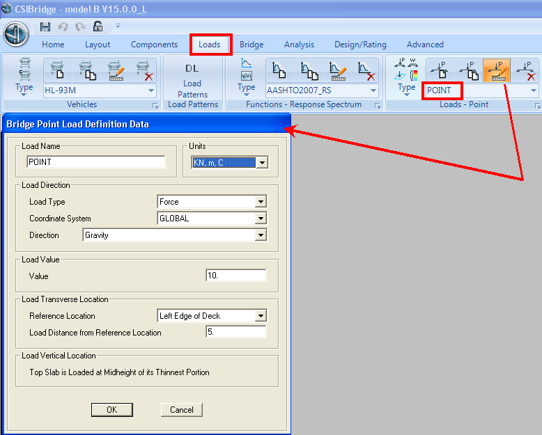
Figure 2 - Define point load
Use the Bridge > Loads > Point Loads command to assign the previously defined point load, as shown in Figure 3:

Figure 3 - Assign point load
Using a similar approach, define and apply line and area loads.
Results
The moment diagrams below (Figures 4-6) depict the midspan moment expected.

Figure 4 - Point load moment diagram
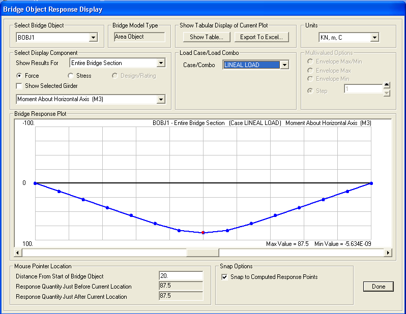
Figure 5 - Line load moment diagram

Figure 6 - Area load moment diagram
Attachments
- CSiBridge V15.0.0 model (zipped .SDB file
...
- )