| Wiki Markup |
|---|
| Action request |
| } Figure 3 seems to be corrupted. Prepare and upload revised figure. |
| Wiki Markup |
|---|
{action-request} {live-template:Tutorial} \\ The purpose of this tutorial is to demonstrate *manual modification of bridge bearings*. The [bridge modeler|kb:Bridge Modeler] automatically generates bearings. Modification is then done outside of the bridge modeler. This tutorial will follow a two-span continuous reinforced-concrete box-girder bridge with four web sections, supported by two bearings at each substructure location. These bearings are centered between each pair of exterior and interior girders. Users may manually modify start-abutment bearing locations through the following process: \\ * Use the Bridge > Update Linked Bridge Model menu to update the structural model. * Uncheck Bridge > Auto Update Linked Bridge Objects to prevent the bridge modeler from overwriting manual changes. * Delete the interior-girder bearing [links|kb:Link] and associated [joints|kb:Joint] automatically produced, as shown in Figure 1: \\ !Manually_modify_bridge_bearings_1.png|align=center,border=1! {center-text}Figure 1 - Delete interior bearings{center-text} \\ * Use the Edit > Move option to move the exterior-girder bearing links and associated joints to the location desired along the transverse direction, as shown in Figure 2: \\ !Manually_modify_bridge_bearings_2.png|align=center,border=1! {center-text}Figure 2 - Move exterior bearings{center-text} \\ * Modify the bearing-link properties as necessary. \\ \\ Additionally, please note that the bottom link connects the [bent cap|kb:Bridge bent] to a joint at the [bearing|kb:Bridge bearings]. These link properties represent those of the bearing. The top link creates a bearing joint at the bottom of the superstructure. The properties assigned to this link simulate a [rigid|kb:Rigid behavior] connection. Further, the body constraint BOBJ-1 connects the start joint of each superstructure girder to joints at the bottom of the superstructure, located just above the bearings, as shown in Figure 3: \\ !Manually_modify_bridge_bearings_3.png|align=center,border=1,width=800pxpx! {center-text}Figure 3 - Bridge bearings{center-text} \\ * Users may then repeat the procedures of this tutorial for the interior bent and end |
The purpose of this tutorial is to demonstrate manual modification of bridge bearings. The bridge modeler automatically generates bearings. Modification is then done outside of the bridge modeler. This tutorial will follow a two-span continuous reinforced-concrete box-girder bridge with four web sections, supported by two bearings at each substructure location. These bearings are centered between each pair of exterior and interior girders. Users may manually modify start-abutment bearing locations through the following process:
- Use the Bridge > Update Linked Bridge Model menu to update the structural model.
- Uncheck Bridge > Auto Update Linked Bridge Objects to prevent the bridge modeler from overwriting manual changes.
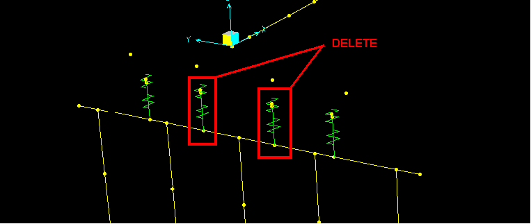
- Delete the interior-girder bearing links and associated joints automatically produced, as shown in Figure 1:
- Use the Edit > Move option to move the exterior-girder bearing links and associated joints to the location desired along the transverse direction, as shown in Figure 2:

- Modify the bearing-link properties as necessary.
Additionally, please note that the bottom link connects the bent cap to a joint at the bearing. These link properties represent those of the bearing. The top link creates a bearing joint at the bottom of the superstructure. The properties assigned to this link simulate a rigid connection. Further, the body constraint BOBJ-1 connects the start joint of each superstructure girder to joints at the bottom of the superstructure, located just above the bearings, as shown in Figure 3:

- Users may then repeat the procedures of this tutorial for the interior bent and end abutment.