| Wiki Markup |
|---|
{live-template:Tutorial}
\\
*Section cuts* are useful for obtaining the resultant forces which act within a specified section-cut plane.
[Section cuts|kb:Section cut] may be defined using any of the following methods:
# Define a quadrilateral cutting plane
\\
\\
# Define a group
\\
\\
# Draw the section cut within the graphical user interface
\\
Each of these section-cut types may be implemented through the procedures described in the following sections:
{on-this-page}
h1. 1. Define a quadrilateral cutting plane
Section-cut forces are the sum of [joint|kb:Joint] forces for all joints which are:
* Included in the section-cut group;
* Within structural objects entirely cut by the quadrilateral plane; and
* Located on the specified side of the section cut.
Joint forces are then summed about the location specified as the Results Reported at the Location parameter.
The procedure for defining a quadrilateral cutting plane is as follows:
* Launch the Section Cut Data form by selecting Define > Section Cuts > Add Section Cut.
* Select Quadrilateral Cutting Planes, then define the plane by specifying its joint coordinates, as shown in Figure 1:
\\
!Section_cut_data_-_quadrilateral_cutting_planes_SAP2000_V12.0.2_form_tutorial.png|align=center,border=0!
{center-text}Figure 1 - Define a quadrilateral cutting plane{center-text}
\\
* For assistance with additional fields on this form, press F1 to access [Context Help|doc:Context Help].
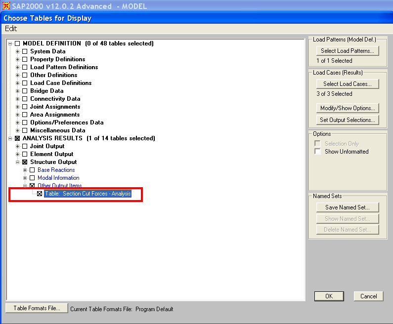
* Once analysis is run, section-cut forces are available in tabular format by selecting Display > Show Tables > Analysis Results > Structure Output > Other Output Items > Table: Section Cut Forces - Analysis, as shown in Figure 2:
\\
!Choose_tables_for_display_section_cut_forces_SAP2000_V12.0.2_form_tutorial.png|align=center,border=0!
{center-text}Figure 2 - Section-cut forces{center-text}
h1. 2. Define a group
Section cuts may also be defined by specifying a group of structural objects. Here, section-cut forces represent the sum of [joint|kb:Joint] forces within those [frame|kb:Frame], [shell|kb:Shell], and [link|kb:Link] objects which are included in the group. As shown in Figure 2, the Section Cut Group must include All joints for which forces should be summed.
\\
!Section_cut_data_-_by_groups_SAP2000_V12.0.2_form_tutorial.png|align=center,border=0!
{center-text}Figure 2 - Section-cut group{center-text}
h1. 3. Draw the section cut within the graphical user interface
Section cuts may be drawn within the graphical user interface by selecting Draw > Draw Section Cut. Section-cut forces will then be displayed on the Section Cut Forces and Stresses form shown in Figure 3:
\\
!Section_cut_stresses_and_forces_SAP2000_V12.0.2_form.png|align=center,border=0!
{center-text}Figure 3 - Directly drawn section cuts{center-text}
h1. See Also
* [Section cuts|kb:Section cut] section
* [Context Help|doc:Context Help] (Output Conventions)
* [Context Help|doc:Context Help] (Example Problems B, N, and |
Section cuts are useful for obtaining the resultant forces which act within a specified section-cut plane.
Section cuts may be defined using any of the following methods:
- Define a quadrilateral cutting plane
- Define a group
- Draw the section cut within the graphical user interface
Each of these section-cut types may be implemented through the procedures described in the following sections:
| On this page |
|---|
1. Define a quadrilateral cutting plane
Section-cut forces are the sum of joint forces for all joints which are:
- Included in the section-cut group;
- Within structural objects entirely cut by the quadrilateral plane; and
- Located on the specified side of the section cut.
Joint forces are then summed about the location specified as the Results Reported at the Location parameter.
The procedure for defining a quadrilateral cutting plane is as follows:
- Launch the Section Cut Data form by selecting Define > Section Cuts > Add Section Cut.
- Select Quadrilateral Cutting Planes, then define the plane by specifying its joint coordinates, as shown in Figure 1:

- For assistance with additional fields on this form, press F1 to access Context Help.
- Once analysis is run, section-cut forces are available in tabular format by selecting Display > Show Tables > Analysis Results > Structure Output > Other Output Items > Table: Section Cut Forces - Analysis, as shown in Figure 2:
2. Define a group
Section cuts may also be defined by specifying a group of structural objects. Here, section-cut forces represent the sum of joint forces within those frame, shell, and link objects which are included in the group. As shown in Figure 2, the Section Cut Group must include All joints for which forces should be summed.

3. Draw the section cut within the graphical user interface
Section cuts may be drawn within the graphical user interface by selecting Draw > Draw Section Cut. Section-cut forces will then be displayed on the Section Cut Forces and Stresses form shown in Figure 3:

See Also
- Section cuts section
- Context Help (Output Conventions)
- Context Help (Example Problems B, N, and S)