Name: | Align solid and hollow sections with different center-of-gravity locations |
Description: | Model relative positive position for frame sections which have identical outlines, but different center-of-gravity locations due to one section being hollow. |
Program: | SAP2000 |
Version: | 14.2.0 |
Model ID: | na |
The internal forces and capacities of a beam are calculated with respect to the cross-section center of gravity. This test problem studies the modeling of a rectangular and continuous beam which is solid along the left segment and hollow along the right. This void is located along the bottom of the element.
Default insertion-point settings locate each segment such that the center of gravity aligns with the element chord. As shown in the image at the top of Figures 1-4, this results in misalignment between each segment because the center of gravity is higher for the hollow section. This may be corrected through either of the following methods:
- Draw element chords to account for the difference in center-of-gravity location, as shown in the middle image of each figure.
- Use a bottom-center insertion point to draw the two segments along the same line as shown in the bottom image of each figure.
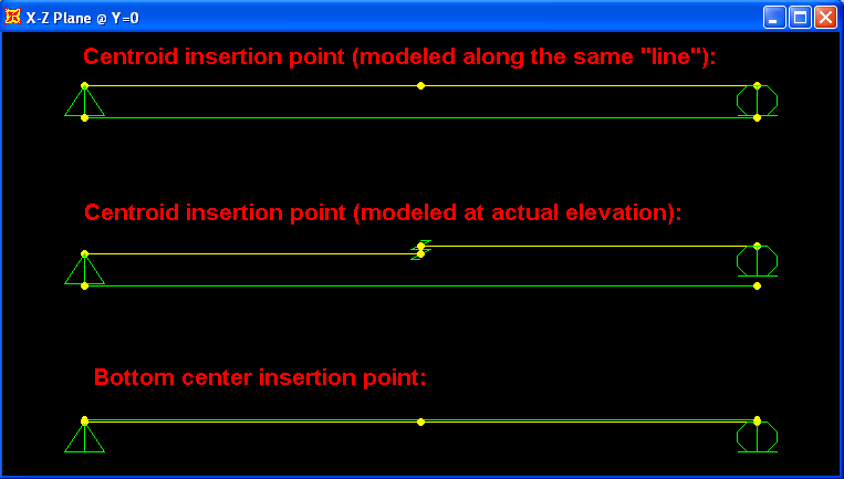
Figure 1 - Modeling approaches

Figure 2 - Corresponding depth profile
To demonstrate how each of these conditions affects response, a straight tendon is modeled below each beam. Tendon deflection and internal moment (relative to cross-section centroid) is presented. Results are correctly reported only for the second and third case, where the solid and hollow sections properly align.

Figure 3 - Displacement

Figure 4 - Moment
Attachments
- SAP2000 V14.2.0 model (zipped SDB file)