The pattern live-load factor (Pllf) is intended to account for variability in the live-load arrangement on a structure. Since live-load pattern is not automated, Pllf approximates its design effect.
When nonzero Pllf is assigned to a frame object, positive design moments are calculated assuming a simply supported condition under live-load application. While this does affect design moments, analysis moments are not affected. Pllf enables users to specify the live-load percentage applied to a frame object for which no continuity is assumed. Negative moments are then redistributed in a manner similar to that of moment redistribution from yielding. As a result, positive midspan-moment values increase. Zero Pllf may be specified to avoid moment redistribution.
Pattern live-load factors may be assigned to individual elements using the Design > Steel Frame Design or Concrete Frame Design > View/Revise Preferences command, as shown in Figure 1:
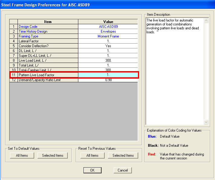
Figure 1 - Pattern live-load factor
Example
The maximum positive midspan design moment induced by uniform dead- and live-load application would be calculated as follows:
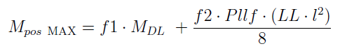
where:
- f1 = code-based dead-load factor (1.2)
- f2 = code-based live-load factor (1.6)
- l = element length
- LL = distributed live load (force/length)
- MDL = positive dead-load moment with actual boundary conditions due to dead load only
- Mpos MAX - maximum positive midspan design moment assuming a simply-supported condition with no continuity for live load
Given point loading, Mpos MAX would be calculated similarly as for uniform loading, in which a simply supported condition is assumed and the live-load factors specified are applied.