Error formatting macro: live-template: java.lang.NullPointerException
Overview
The goal of this tutorial is to explain how to model pinned connection between crossing members as shown in the figure below for location E:

Unknown macro: {center-text}
Figure 1 - System with crossing member
Create model
- Create new model using the "Grid Only" template.
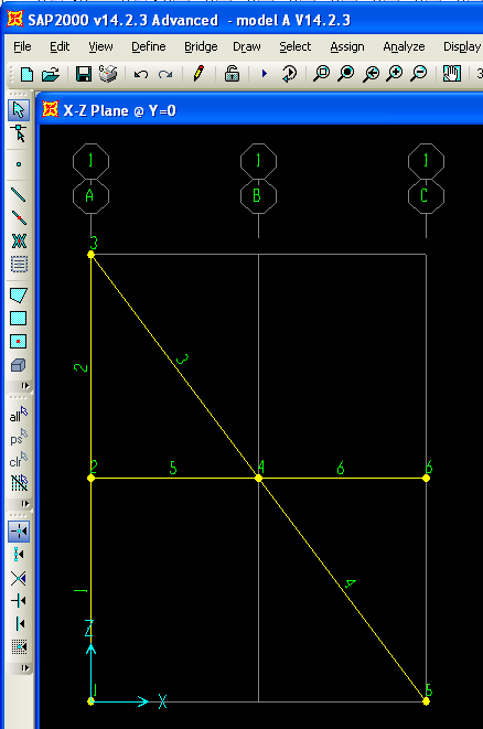
- Draw 6 frame elements in X-Z plane as shown in the figure below:
Unknown macro: {center-text}
Figure 2 - SAP2000 analytical model
- Select members 3 and 5 and assign moment M33 end release to the start joint of the members using the "Assign > Frame > Releases/Partial Fixity" menu command.
- Select joint 4 (the joint at which the horizontal and inclined members cross) and use the "Edit > Edit Points > Disconnect" menu command to create for separate joints at this location, one for each of the connected members. This will replace joint 4 by four separate joints (numbered 4, 7, 8, 9) as shown in the figure below:

Unknown macro: {center-text}
Figure 3 - Crossing-member joint specification
- To model continuity for the horizontal member and the inclined member, merge joints 4 and 7 and also merge joints 8 and 9 as follows:
- Use "Select > Select > Labels" menu command to select joints 4 and 7 (ie. the "continuity joints" for the inclined member) and then use "Edit > Edit Points > Merge Joints" command to merge the two selected joints to make the inclined member continuous.
- Repeat the same procedure for joints 8 and 9 to make the horizontal member continuous.
- Use "Select > Select > Labels" menu command to select joints 4 and 7 (ie. the "continuity joints" for the inclined member) and then use "Edit > Edit Points > Merge Joints" command to merge the two selected joints to make the inclined member continuous.
- Select the two resulting joints at the intersection of the inclined and horizontal members and assign equal constraint for all translational degrees of freedom to make model the pinned connection (alternatively you could use link to connect the two joints.
- Assign pinned support to joint 1 and roller support to joint 2.
- Use "Analyze > Set Analysis Options > XZ Plane" menu command to model the structure in 2D.
- Assign 100kN load in gravity direction to joint 6 using a "LOAD" load pattern:

Unknown macro: {center-text}
Figure 4 - Load application
Results
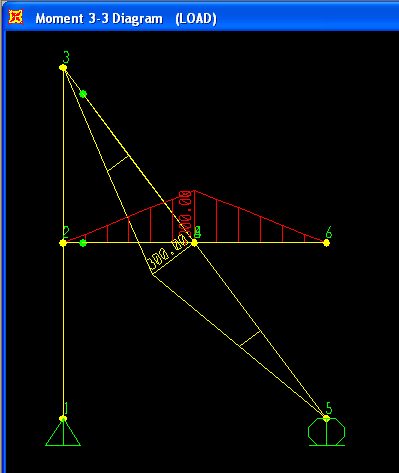
The resulting moment diagram is shown in the figure below:
Unknown macro: {center-text}
Figure 5 - Flexural response
See Also
References
- Alongkorn Lamom, Thaksin Thepchatri, and Wanchai Rivepiboon: Hybrid Connection Simulation Using Dynamic Nodal Numbering Algorithm
 ; American Journal of Applied Sciences 7 (8): 1174-1181, 2010
Attachments
- [SAP2000 V14.2.3 model|Modeling pinned connection between crossing members^model A V14.2.3.zip] - relevant SAP2000 model (zipped SDB file)