Error formatting macro: live-template: java.lang.NullPointerException
This tutorial describes the modeling process for a composite bridge composed of a concrete slab over steel girders with variable flange thickness.
Modeling steps
To obtain the variable flange thickness desired, users should assign non-prismatic girder sections to the bridge deck section.
Create new model from template
- Select File > New Model > KN, m, C units > Quick Bridge template.
- Set span lengths to '30; 30', and select Steel Girder as the bridge deck-section type.
Define non-prismatic steel girder sections
- Select Define > Section Properties > Frame Sections
- Rename the default girder section FSEC1 to 'GRD 50mm Flange'.
- Copy the 'GRD 50mm Flange' section, change the thickness for the top and bottom flanges to 75mm, change the section depth to 1.27m (maintaining consistency with previous web depth), and then save the section as 'GRD 75mm Flange'.
- Select Add New Property > Frame Section Property (other) > Non-prismatic Section to create non-prismatic sections 'GRD span1' and 'GRD span2' as follows: (1) for 'GRD span1', specify the 'GRD 50mm Flange' section for the first 20m of length, and the 'GRD 75mm Flange' section for the next 10m of length; (2) for 'GRD span2', specify the 'GRD 75mm Flange' section for the first 10m of length, and the 'GRD 50mm Flange' section for the next 20m of length. This process is shown in Figure 1:
- Rename the default girder section FSEC1 to 'GRD 50mm Flange'.

Unknown macro: {center-text}
Figure 1 - Section definition
Create bridge deck sections
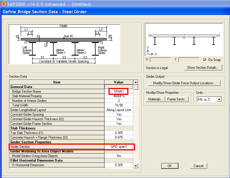
- Use the Bridge > Deck Section > Add Copy of Section menu command to create bridge sections to be assigned to the first and the second spans of the bridge object. Name these sections SPAN1 and SPAN2, and utilize the previously-defined non-prismatic girder sections 'GRD span1' and 'GRD span2', as shown in Figure 2:
Unknown macro: {center-text}
Figure 2 - Bridge section data
Assign bridge deck sections to the bridge object
- Use the Bridge > Bridge Objects > Modify/Show Bridge Object > Modify/Show Assignments, Spans menu command to assign the previously-defined bridge deck sections SPAN1 and SPAN2 to the first and second spans of the bridge object, as shown in Figure 3:

Unknown macro: {center-text}
Figure 3 - Span assignments
- Set OpenGL graphics using the Option > Graphics Mode > OpenGL menu command
- Use View > Set Display Options > Show Extruded Shape to display the extruded shape of the bridge. Please note that there is a graphical discontinuity, though the frame elements are inserted such that top-of-web locations form a continuous line. This may be checked by reviewing the insertion point (top center) and offsets. The extruded view is shown in Figure 4:

Unknown macro: {center-text}
Figure 4 - Extruded view