This space is devoted to CSiBridge. Please visit the Technical Knowledgebase for documentation on topics and features common to all CSI Software.
|

|
|
|
CSiBridge is a software tool produced specifically for the engineering of bridge systems. Using CSiBridge, suspension, cable-stay, elevated roadway, and any other types of bridge systems may be modeled and designed to suit a variety of purposes, including means for crossing water, linking points between shear terrain, or extending over highway infrastructure.
|

|
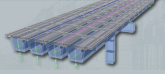
Modeling of Bridge Systems
An object-oriented approach drives the modeling of bridge systems. This way, designers assign bridge composition as an assembly of objects (roadway superstructure, substructure, abutments, piers, foundation system, etc.) before the SAPFire analysis engine, integral to CSI Software, automatically transfers the object-based model into a mathematical finite element model by meshing the material domain and assigning material properties. This object-oriented approach simplifies and expedites the modeling process, saving engineers the need to directly define, mesh, link, and constrain all material volumes.
CSiBridge also allows engineers to import model data from Dwg/Dxf, IGES, CIS/2 STEP, and Land XML file formats, or export to PERFORM-3D, MS Access, and CIS/2 STEP, all following IFC standards.
Loading and Analysis
|
|


|
|
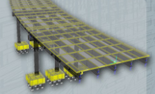
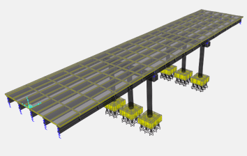
After modeling, CSiBridge provides options for the assignment of load cases and combinations. Vehicle, seismic, and wind loading are generated according to building code (AASHTO LRFD, Canadian, etc.) and assigned according to model geometry. To make CSiBridge intuitive and practical, CSI developed a series of templates for the assignment and enveloping of load conditions.
After the original object-based model has been translated into a finite element model and subjected to load cases and combinations, the analysis process follows directly.
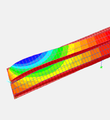
Analysis capabilities go well beyond elastic performance into the assessment of inelastic behaviors. Geometric and material nonlinearities provide insight into strength, ductility, and other performance measures critical to response under extreme scenario. Static pushover and dynamic analyses (steady state, response spectrum, and time history) provide further insight into earthquake resilience. Substructure hinging properties are customizable.
|
Additional analysis features may account for creep and shrinkage behavior, post-tensioning with optional automatic cable tensioning, staged construction effects inherent to segmental construction, buckling, camber and shape finding.
|
|
|
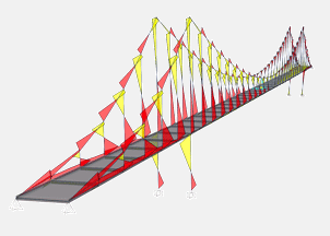
Design and Output
An automatic design process couples with analysis procedures to coordinate and optimize the resizing of bridge components. For reinforced concrete systems, CSiBridge optimizes rebar sizing under the same procedure.
Customizable reports present analysis and design details in a variety of formats. Moment, shear, and axial response data and diagrams in 2D and 3D views, seismic displacement capacity, demand-capacity ratio, load rating per classification, influence surface plots for displacement, reaction, and frame, shell, solid, or link response are all options for output generation.