Tutorial
Name: | Manual modeling of wall-type bents |
Description: | This tutorial describes a manual modeling process for wall-type bents within bride objects. |
Program: | SAP2000 |
Version: | 14.2.2 |
Model ID: | na |
Modeling steps
- Use the Quick Bridge template (File > New Model) to create a new bridge model with a 'Conc. Tee Beam' bridge-deck section.
Please note that a single column represents the default interior bent, as shown in Figure 1:

Figure 1 - Default interior bent
- Select the frame element which represents the bent cap, and select all joints located on this element, as shown in Figure 2:
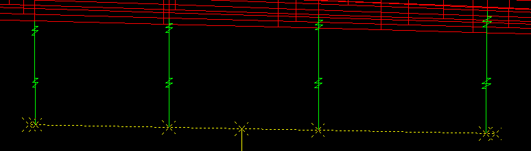
Figure 2 - Selected frame element and joints
- Use the Edit > Edit Lines > Edit Frames menu command to break the frame element at its intersection with the selected joints.
Re-select the six frame elements created by dividing the original bent cap and using the Edit > Extrude > Extrude Lines to Areas menu command to extrude the bent cap into the wall. Enter -31 for increment dz, 10 for Number, and select the Delete Source Objects option. This will create a wall of approximately the same height as the original column. The process is shown in Figure 3:
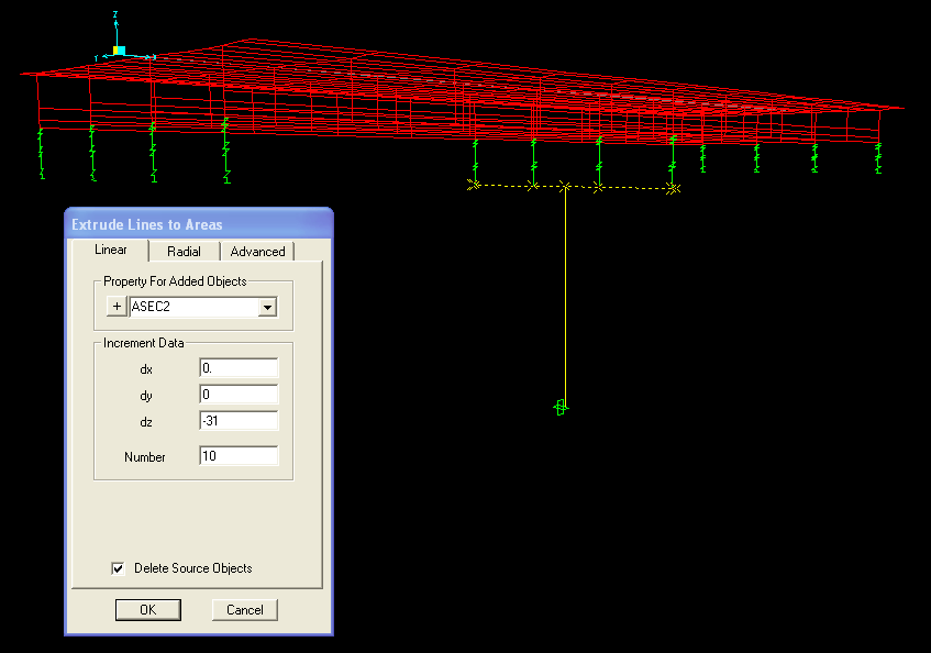
Figure 3 - Create wall-type bent
- Select the bottom joints of the wall and assign constraints using the Assign > Joint > Restraints option. The completed model is shown in Figure 4:
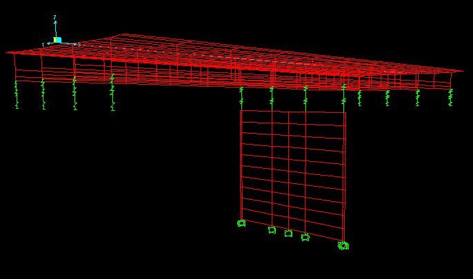
Figure 4 - Wall-type bent
- Users may also model wall properties by changing the section properties of areas assigned to the wall. If the bent cap is integral to the superstructure, the wall support may be created below the bent cap, and these components may be connected with links which represent the characteristics along this interface (such as with a shear only connection).