Tutorial
Name: | Joint-pattern first steps |
Description: | This tutorial provides an introduction to the assignment of joint patterns. |
Program: | SAP2000 |
Version: | 12.1.0 |
Model ID: | na |
To obtain the vertical loading on a slab element which is modeled using a fairly fine mesh, users may implement a joint pattern through the following process:
- For each loading patch, or set of patches which act together, select Define > Joint Pattern to define a joint pattern, as shown in Figure 1:

Figure 1 - Name joint patterns
- Select joints which are contained within the patch or patches. Next, select Assign > Joint Pattern, then assign a dimensionless scale factor D, such as 1.0. This process is shown in Figure 2:
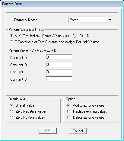
Figure 2 - Pattern data
- Select the slab elements, then select Assign > Area Loads > Surface Pressure to assign pressure (force/area) such that it acts downward on the top face, according to the appropriate load pattern. This menu is shown in Figure 3:

Figure 3 - Area surface pressure load
- The pressure on each element will be interpolated from the product between joint-pattern values and the pressure assigned, which is 5.0 kN/m in this example. If only one element joint has a nonzero pressure, a quarter of the load will be applied. Load pressure is multiplied by element tributary area such that users need not manually calculate nodal forces.
Display joint pattern
- To graphically display the joint-pattern assignment, select Display > Show Misc Assigns > Joints.
- Select Display > Show Load Assign > Area Surface Pressure Values to display the area load assigned to each joint.