| Wiki Markup |
|---|
{live-template:Tutorial}
h1. Overview
This tutorial describes how to model a pin connection between crossing members. Instruction will consider the structural system shown in Figure 1. The critical [joint|kb:Joint] within this system is located as point E. To induce structural response, a 100kN load will be applied, in the gravity direction, at the end of the horizontal element.
\\
!fig01 - geometry.png|align=center,border=1!
{center-text}Figure 1 - System with crossing member{center-text}
h1. Modeling
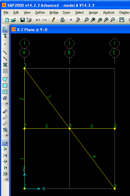
To begin, use [SAP2000|sap2000:home] to create the model shown in Figure 2:
\\
!fig02 - members.png|align=center,border=1!
{center-text}Figure 2 - SAP2000 model{center-text}
\\
This model may be generated through the following process:
# Create a new model using the Grid Only template.
\\
\\
# In the X-Z plane, draw the six frame elements shown in Figure 2.
\\
\\
# Select members 3 and 5, then use the Assign > Frame > Releases/Partial Fixity command to assign moment M33 end releases to member start-joints.
\\
\\
# Select joint 4, the point of pin connection, then use the Edit > Edit Points > Disconnect command to create four separate joints at this location, one for each of the coincident members. The new joints will be numbered 4, 7, 8, and 9, as shown in Figure 3:
\\
\\
\\
!fig03 - disconnected joints.png|align=center,border=1!
\\
{center-text}Figure 3 - Revised joints at the pin-connection {center-text}
\\
\\
# To model continuity between the horizontal and inclined members, merge joints 4 and 7, then 8 and 9 as follows:
\\
\\
## Use the Select > Select > Labels command to select joints 4 and 7, known as the continuity joints of the inclined member. Use the Edit > Edit Points > Merge Joints command to merge the two joints selected. The inclined member will then be continuous.
\\
\\
## Repeat the same procedure for joints 8 and 9 to establish continuity along the horizontal member.
\\
\\
# Select the two resultant joints located at the pin connection. Assign an [equal constraint|kb:equal constraint] to all translational degrees of freedom. This models the pinned connection. As an alternative, a [link|kb:link] element may be used to connect the two joints.
\\
\\
# Assign a pin support to joint 1, and a roller support to joint 2.
\\
\\
# Use the Analyze > Set Analysis Options > XZ Plane command to constrain the structure within the 2D plane.
\\
\\
# Use the LOAD [load pattern|kb:Load pattern] to assign a 100kN load, in the gravity direction, at joint 6. The resultant configuration is shown in Figure 4:
\\
\\
\\
!fig04 - load assignment.png|align=center,border=1!
\\
{center-text}Figure 4 - Load application{center-text}
h1. Results
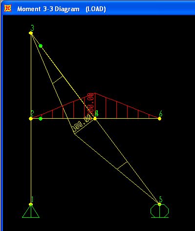
As a validation of successful modeling, analysis will then generate the moment diagram shown in Figure 5:
\\
!fig05 - moment diagram.png|align=center,border=1!
{center-text}Figure 5 - Flexural response{center-text}
h1. See Also
* [Special joint|kb:special joint] article
h1. References
* Lamom, A., Thepchatri, T., Rivepiboon, W. (2012). {new-tab-link:http://thescipub.com/abstract/10.3844/ajassp.2010.1174.1181}Hybrid connection simulation using dynamic nodal numbering algorithm{new-tab-link}. _American Journal of Applied Sciences, 7_(8), 1174-1181.
h1. Attachments
* [SAP2000 V14.2.3 model |Modeling a pin connection between crossing members^model A V14.2.3.zip] (zipped SDB |
Overview
This tutorial describes how to model a pin connection between crossing members. Instruction will consider the structural system shown in Figure 1. The critical joint within this system is located as point E. To induce structural response, a 100kN load will be applied, in the gravity direction, at the end of the horizontal element.

Modeling
To begin, use SAP2000 to create the model shown in Figure 2:
This model may be generated through the following process:
- Create a new model using the Grid Only template.
- In the X-Z plane, draw the six frame elements shown in Figure 2.
- Select members 3 and 5, then use the Assign > Frame > Releases/Partial Fixity command to assign moment M33 end releases to member start-joints.
- Select joint 4, the point of pin connection, then use the Edit > Edit Points > Disconnect command to create four separate joints at this location, one for each of the coincident members. The new joints will be numbered 4, 7, 8, and 9, as shown in Figure 3:

- To model continuity between the horizontal and inclined members, merge joints 4 and 7, then 8 and 9 as follows:
- Use the Select > Select > Labels command to select joints 4 and 7, known as the continuity joints of the inclined member. Use the Edit > Edit Points > Merge Joints command to merge the two joints selected. The inclined member will then be continuous.
- Repeat the same procedure for joints 8 and 9 to establish continuity along the horizontal member.
- Use the Select > Select > Labels command to select joints 4 and 7, known as the continuity joints of the inclined member. Use the Edit > Edit Points > Merge Joints command to merge the two joints selected. The inclined member will then be continuous.
- Select the two resultant joints located at the pin connection. Assign an equal constraint to all translational degrees of freedom. This models the pinned connection. As an alternative, a link element may be used to connect the two joints.
- Assign a pin support to joint 1, and a roller support to joint 2.
- Use the Analyze > Set Analysis Options > XZ Plane command to constrain the structure within the 2D plane.
- Use the LOAD load pattern to assign a 100kN load, in the gravity direction, at joint 6. The resultant configuration is shown in Figure 4:

Results
As a validation of successful modeling, analysis will then generate the moment diagram shown in Figure 5:
See Also
- Special joint article
References
- Lamom, A., Thepchatri, T., Rivepiboon, W. (2012). . American Journal of Applied Sciences, 7(8), 1174-1181.
Attachments
- SAP2000 V14.2.3 model (zipped SDB file)